Introduction to Electrical Protection Devices
In high-performance electrical systems—whether for aerospace, military, or motorsport applications—protection devices are critical components that safeguard against overcurrent conditions, short circuits, and other electrical faults. These devices not only protect expensive equipment but can also prevent catastrophic failures that might lead to fires, loss of critical systems, or complete vehicle/aircraft shutdown.
This guide examines three primary types of protection devices used in high-performance applications:
- Relays - Electromechanical or solid-state switches controlled by electrical signals
- Fuses - Single-use overcurrent protection devices
- Circuit Breakers - Resettable overcurrent protection devices
Understanding the unique characteristics, applications, and selection criteria for each type is essential for designing reliable electrical systems that meet MIL-SPEC standards and perform in demanding environments.
Relays: Controlled Switching for Critical Systems
How Relays Work
At its core, a relay is an electrically operated switch. It uses a small control circuit to switch a much larger power circuit on or off, providing isolation between the controlling circuit and the controlled circuit. This isolation is particularly valuable in high-voltage or high-current applications where direct switching would be impractical or dangerous.
The basic components of an electromechanical relay include:
- Electromagnet (Coil) - Creates magnetic field when energized
- Armature - Moves in response to the electromagnet
- Contacts - Connect or disconnect the circuit
- Return Spring - Returns armature to resting position when de-energized
- Frame - Houses and supports all components
Key Advantages of Relays
- Electrical isolation between control and power circuits
- Ability to control high-current circuits with low-current signals
- Multiple circuit control from a single switch
- Reduced voltage drop compared to semiconductor switches
- Visual indication of switching status (in LED-equipped models)
- Inherent protection against electrical noise and EMI
- Bidirectional current flow capability
- Excellent overload handling for transient spikes
Types of Relays for High-Performance Applications
Several specialized relay types are used in aerospace, military, and motorsport applications:
| Relay Type | Description | Common Applications |
|---|---|---|
| Automotive Relays | Compact relays designed for 12V/24V automotive systems, available in various current ratings | Lighting systems, fuel pumps, cooling fans, starter motors |
| Military-Grade Relays | Ruggedized relays meeting MIL-PRF-39016 or similar standards with enhanced environmental protection | Defense vehicles, weapons systems, battlefield communication equipment |
| Aerospace Relays | Hermetically sealed relays certified for aerospace use with extreme temperature tolerance | Aircraft power distribution, avionics, landing gear systems |
| Solid-State Relays (SSR) | Electronic relays with no moving parts using semiconductor switching devices | Applications requiring high reliability, fast switching, or immunity to vibration |
| Time Delay Relays | Relays with built-in timing functions to delay activation or deactivation | Sequential system start-up, cooling system control, safety interlocks |
Spotlight: Aftermarket Industries PR40 Relay
MIL-SPEC Performance: PR40 Relay with LED Indicator
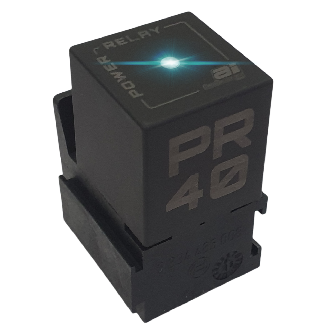
The Aftermarket Industries PR40 Relay represents the pinnacle of automotive relay technology designed for motorsport and high-performance applications. This 40-amp continuous duty relay combines military-grade durability with innovative features:
- 2-Way Fault Detection LED - Visual indication of relay status and wiring faults
- Surge Protection Diode - Prevents back EMF damage to sensitive electronics
- 10G Vibration Resistance - Maintains reliable operation in high-vibration environments
- IP50 Environmental Protection - Resists dust and moisture intrusion
- Wide Temperature Range - Operates from -40°C to 85°C
- Fast Response Time - 5ms switching for critical applications
Relay Selection Criteria
When selecting relays for high-performance applications, consider these factors:
- Voltage Rating - Both coil voltage (control side) and contact voltage (switched side)
- Current Rating - Maximum continuous current and inrush/surge current handling
- Contact Configuration - SPST, SPDT, DPDT, etc. depending on switching requirements
- Environmental Protection - IP rating for dust/moisture resistance
- Temperature Range - Operating temperature extremes for the application
- Vibration/Shock Resistance - Particularly important in motorsport and aerospace
- Switching Speed - Activation and deactivation times
- Life Expectancy - Mechanical and electrical cycle ratings
- Mounting Options - Socket, PCB, chassis, or panel mounting
- Special Features - LED indicators, suppression diodes, latching function
Fuses: Single-Use Protection Devices
How Fuses Work
Fuses are simple yet effective overcurrent protection devices that operate on a fundamental principle: they contain a metal wire or strip that melts when too much current flows through it, interrupting the circuit. This sacrificial design provides reliable protection but requires replacement after activation.
The key components of a fuse include:
- Element - The metal strip or wire that melts during an overcurrent condition
- Body - The insulating container that houses the element
- End Caps/Terminals - The conductive ends that connect to the circuit
- Arc Suppression Medium - In some fuses, silica sand or other materials to quench the arc
Types of Fuses for High-Performance Applications
The following fuse types are commonly used in aerospace, military, and motorsport applications:
| Fuse Type | Description | Common Applications |
|---|---|---|
| Blade Fuses (ATO/ATC) | Plastic-body automotive fuses with blade contacts, color-coded by current rating | Modern automotive circuits, standard in most racing vehicles |
| Glass Tube Fuses | Transparent glass tubes with visible elements and metal end caps | Older automotive systems, electronics, instrumentation |
| Ceramic Fuses | High-temperature ceramic body fuses for extreme conditions | High-temperature environments, power circuits |
| MIDI/AMI Fuses | Medium-sized bolt-down fuses for higher current applications | Main power distribution, high-current systems (30-150A) |
| ANL Fuses | High-current fuses with rectangular body and bolt-down connections | Alternator protection, battery isolators, amplifiers (100-500A) |
| Military Qualified Fuses | Fuses meeting MIL-PRF-23419 or similar specifications | Defense equipment, military vehicles, aircraft systems |
Fuse Selection and Sizing
Proper fuse selection requires careful consideration of several factors:
- Current Rating - The amperage at which the fuse will open
- Voltage Rating - Maximum voltage the fuse can safely interrupt
- Speed Rating - Fast-blow or time-delay characteristics
- Breaking Capacity - Maximum fault current the fuse can safely interrupt
- Physical Size - Form factor and mounting considerations
- Environmental Factors - Temperature, vibration, and humidity resistance
MIL-SPEC Fuse Sizing Formula
According to MIL-SPEC standards, proper fuse sizing follows this calculation:
This formula provides a 25% safety margin above the maximum expected continuous current draw of the circuit, preventing nuisance trips while maintaining adequate protection. After calculation, round up to the next standard fuse size.
Standard Fuse Sizes
Standard automotive and aerospace fuse ratings are typically available in these amperage values:
Circuit Breakers: Resettable Protection
How Circuit Breakers Work
Circuit breakers provide overcurrent protection like fuses but with a crucial advantage: they can be reset after tripping rather than requiring replacement. This makes them ideal for applications where occasional overcurrent situations may occur, or where quick restoration of power is critical.
Most circuit breakers operate using one of these principles:
- Thermal - Uses a bimetallic strip that bends when heated by overcurrent
- Magnetic - Uses an electromagnet that trips when current exceeds threshold
- Thermal-Magnetic - Combines both mechanisms for comprehensive protection
- Hydraulic-Magnetic - Uses magnetism and fluid dynamics for precise trip characteristics
Types of Circuit Breakers for High-Performance Applications
Several specialized circuit breaker types are used in aerospace, military, and motorsport applications:
| Circuit Breaker Type | Description | Common Applications |
|---|---|---|
| Automotive Push-to-Reset | Manual reset breakers with push-button operation | Accessory circuits, non-critical systems |
| Automotive Type III | High-performance breakers with cycling capability | Critical vehicle systems, racing applications |
| Aerospace MS3320 | Military-standard toggle breakers meeting MS3320 specification | Aircraft systems, military vehicles |
| Remote Reset Breakers | Electrically controlled breakers that can be reset remotely | Inaccessible locations, automated systems |
| Surface Mount Breakers | Low-profile breakers for space-constrained applications | Electronic control systems, instrumentation |
Circuit Breaker vs. Fuse: When to Use Each
The choice between circuit breakers and fuses depends on several factors:
Choose Circuit Breakers When:
- Quick circuit restoration is required
- Circuit experiences occasional legitimate current spikes
- Protection device is in a difficult-to-access location
- System requires frequent testing or maintenance
- Application can justify the higher initial cost
- Precise trip characteristics are needed
- Personnel may not have replacement fuses available
Choose Fuses When:
- Lower initial cost is a priority
- Fast response to short circuits is critical
- Space constraints exist (fuses are typically smaller)
- Circuit needs protection from severe overcurrent events
- Higher reliability is required (fewer mechanical parts)
- Visual indication of circuit status is valuable
- Application has weight restrictions
Integrated Protection Systems
Modern high-performance vehicles and aerospace systems frequently employ integrated protection strategies that combine multiple device types for comprehensive protection. These approaches may include:
1. Tiered Protection Architecture
This strategy implements protection at multiple levels within the electrical system:
- Main Circuit Protection - High-current fuses or breakers at battery and primary distribution points
- Branch Circuit Protection - Mid-range fuses protecting groups of related components
- Component-Level Protection - Individual fuses for specific components
- Electronic Protection - Semiconductor-based current limiting in sensitive circuits
2. Relay-Controlled Distribution Systems
These systems use relays to control power distribution with integrated protection features:
Example: PR40 Relay in Integrated System
The Aftermarket Industries PR40 relay excels in integrated protection systems by combining switching capability with diagnostic features. Its LED indicator provides instant feedback on circuit status, allowing quick identification of:
- Normal Operation (steady green LED)
- Open Circuit Conditions (no LED illumination)
- Excessive Current Draw (flickering LED)
- Circuit Fault (red LED)
This built-in diagnostics capability makes the PR40 ideal for critical circuits where quick fault identification is essential, such as fuel pump systems, ECU power supplies, and primary lighting circuits.
3. Power Distribution Modules (PDMs)
Advanced power distribution modules integrate multiple protection technologies:
- Solid-state switches with current monitoring
- Programmable overcurrent thresholds
- Auto-reset or permanent shutdown options
- CAN bus connectivity for system integration
- Data logging of electrical system performance
These systems are becoming standard in high-end motorsport applications but typically still incorporate traditional relays like the PR40 for high-current switching of critical loads.
Installation Best Practices
Relay Installation Guidelines
Do's
- Mount relays in clean, dry locations away from heat sources
- Use properly sized wire for both control and load circuits
- Include a suppression diode for inductive loads
- Ensure solid, corrosion-resistant connections
- Label relays and wiring for future maintenance
- Verify proper relay orientation during installation
- Test relay function before completing installation
Don'ts
- Mount relays near exhaust components or direct heat sources
- Exceed relay's rated current or voltage specifications
- Leave relay terminals exposed to moisture or contamination
- Use undersized wire that could restrict current flow
- Install without proper circuit protection (fusing)
- Daisy-chain multiple high-current loads through a single relay
- Rely on the relay's case as a grounding point
Fuse and Circuit Breaker Installation Guidelines
Proper installation of protection devices is critical for system safety:
- Install protection devices as close as possible to the power source
- Use fuse holders or circuit breaker mounts rated for the application
- Ensure protection devices are accessible for inspection and replacement/reset
- Protect all positive conductors from potential short circuits
- Use appropriate terminals and connectors for the current level
- Implement proper strain relief to prevent wire fatigue at connection points
- Create a protection device map/diagram for maintenance reference
Recommended Protection Devices
Based on our extensive testing and field experience, we recommend these high-performance protection components for aerospace, military, and motorsport applications:
Premium Relay
Aftermarket Industries PR40
40A relay with LED status indicator and surge protection
- 40A continuous duty rating
- 2-Way Fault Detection LED
- IP50 environmental protection
- -40°C to 85°C operating range
Recommended Fuses
Littelfuse MIDI Fuses
High-performance fuses for demanding applications
- 30A to 150A ratings
- 32V DC rating
- Bolt-down installation
- Ideal for primary protection
Circuit Breakers
Tyco/TE Connectivity W-Series
Military-grade circuit breakers for critical systems
- 5A to 100A ratings
- Compatible with MIL-SPEC requirements
- Trip-free design
- Temperature compensated
Conclusion
Effective protection devices are the foundation of reliable electrical systems in aerospace, military, and motorsport applications. By properly selecting, sizing, and installing relays, fuses, and circuit breakers, engineers can create systems that perform reliably in the most demanding environments.
The Aftermarket Industries PR40 relay stands out as a premium solution for high-performance applications, offering an ideal combination of robust switching capacity, built-in diagnostic capabilities, and MIL-SPEC durability. When paired with appropriately sized fuses or circuit breakers, it forms the core of a comprehensive protection strategy for critical electrical systems.
For personalized advice on selecting protection devices for your specific application, contact our engineering team or use our Wire Gauge Calculator to determine the optimal wire size and protection specifications for your electrical system.
Related Tools & Resources
References & Further Reading
- MIL-PRF-39016 - Military Specification for Relays, Electromagnetic, General Specification
- MIL-PRF-23419 - Military Specification for Fuses, Instrument, Power, and Telephone
- SAE J1171 - External Ignition Protection for Marine Electrical Devices
- MS3320 - Military Standard for Circuit Breakers
- SAE J553 - Circuit Breakers